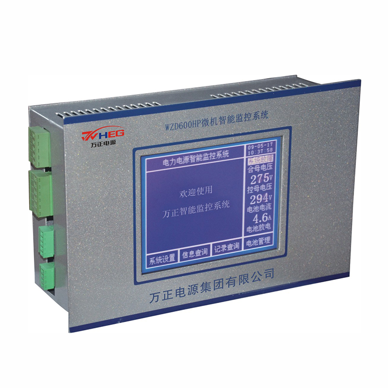
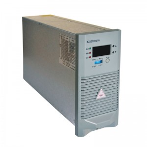
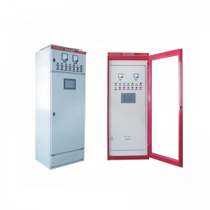
WZD200C-600C series microcomputer touch screen monitoring system
1. Performance characteristics
1.1 Detection function: The system includes main monitoring, AC detection unit, switch unit, battery inspection and insulation detection unit, which can accurately monitor various operating parameters of the system, and is also compatible with communication modules and inverter modules;
1.2 Control functions; including intelligent charging and discharging management of the battery (strictly controlling the charging voltage and current of the battery to prolong the service life of the battery), intelligent AC two-way automatic switching, module switching and voltage and current control;
1.3 Human-machine interface: large-screen liquid crystal display (one screen can display 20*15 Chinese characters, and can also display the charge and discharge curve of the battery pack), touch screen touch operation, all Chinese characters are displayed, and the operation is easy;
1.4 Alarm function: when the system is abnormal, it will immediately generate sound and light alarm, start the fault relay and transmit it to the background through RS485, and the main monitoring display will automatically jump to the fault information display screen, which is convenient for the unattended scientific management of the computer room;
1.5 Setting function; the system can be flexibly configured (such as whether the bus is segmented or not, the number of modules, the number of battery packs, the number of inspection instruments and insulation detectors, etc.), set the upper and lower alarm limits of each parameter, and set the current sensor transformation ratio , Configure the fault output node;
1.6 The standard communication protocol of the Ministry of Electric Power is adopted, and the RS485 communication interface is provided, which is convenient for docking with the electric power automation system, and realizes the "four remote" function of the power supply system, so as to achieve the purpose of unattended automatic management; (the communication method with the background is; through the main screen The back of the 1st line "Power supply intelligent monitoring system" indicates whether the communication is normal with different symbols 1. When there is no response, it means that no data from the background has been received. The problem is that there may be a problem with the hardware wiring; 2. When it is found that there is When "." is flashing, it means that data has been received, but the data packet is wrong, which may be a problem with the address or baud rate setting; 3. When it is found that there is a ":" flashing, it means that the data packet has been received, but the verification is not correct. There is a problem with the byte; 4. When it is found that there is "*" flashing, it means that the background communication is successful; 5. At the bottom left of the monitoring rear panel, when the green light flashes, it means that the monitoring data is sent, and when the yellow light flashes, it means monitoring Received data from outside)
1.7 Operation authority management mode, the system has factory password and super password, and unauthorized personnel can only do some simple query operations to ensure the safe and reliable operation of the system.
1.8 It can directly carry a variety of digital or analog modules, without the need for additional protocol conversion boxes or digital-to-analog conversion boxes.
1.9 It has the function of busbar insulation detection, and can also be connected to 120-way branch circuit segmentable insulation units.
1.10 It can detect a 3-way AC voltage. It can also be connected to an AC unit that can detect two-way 3-phase voltage detection and control.
1.11 Switch output can be set independently, among which output 2, 3 and 4 can be set as silicon chain control.
1.12 Up to 160 switch units can be connected.
1.13 Up to 120 switch status units can be connected.
1.14 Up to two groups of 120 battery inspection units can be attached
1.15 Touch the upper left corner of the screen 3 times in a row to reset the system
1.16 In the upper left corner of the screen, when the system is configured with a digital module, "M" will flash when the communication is successful. When the system is configured with a battery unit, a "D" will flash when the communication is successful. When the system is configured with an insulating unit, the communication is successful. "J" will flash;
1.17 itself has 16 switch signal input points. When the number of switches is set to 0, the alarm is displayed as the word printed on the shell; when it is set to 8, the alarm is displayed as a number; for example, when the 15th channel is grounded, the display "Switch 01 SPD"; when set to 8, it displays "Switch 01 Switch 15"
2.the organizational structure of the monitoring system
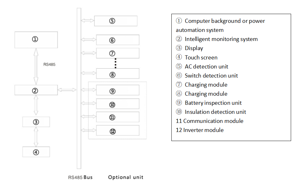
The second-generation monitoring system is flexibly compatible with the detection and control of various equipment in the power system. The system mainly includes main monitoring, AC detection unit, switch value detection unit, battery inspection unit, and insulation detection unit. The switch unit can be expanded up to 4 units; the charging module can control up to 32 units; the battery inspection can inspect up to 2 groups of 120-cell battery packs; the insulation detection unit can be expanded to up to 4 units with a total of 120 output circuits . For example, the communication module and the inverter module can configure the protocol conversion unit according to the situation. The system organization structure is shown in the following figure:
3. Product installation size
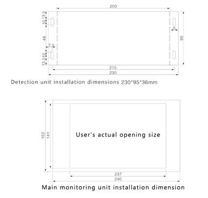
Considering the customer's installation habits and convenience, the system consists of two structures, namely the main monitoring unit and the detection unit. Open a rectangular hole of corresponding size on the panel of the cabinet, put the main monitor into it, and then tighten the screw on the card on the reverse side to firmly fix it on it. Please open the hole according to the given size without leaving any excess. quantity. Users only need to open a 237*141mm rectangular hole on the panel of the cabinet.
5. Definition of wiring port
A brief description of this power supply intelligent touch screen monitoring system:
1. The system is powered by DC (85VDC-320VDC), which comes from the combined bus voltage
2. It can directly control a variety of digital or analog modules, without the need for additional protocol conversion boxes or digital-to-analog conversion boxes
3. The system has the function of busbar insulation monitoring, and can be plugged with 120-channel segmentable branch insulation monitoring units
4. It can detect one-way three-phase AC voltage. It can also be externally connected to two-way three-phase voltage detection and control AC detection unit
5. Switch output can be set independently, among which output 2, 3 and 4 can be set as silicon chain control
6. Up to 160 switch detection units can be connected externally
7. Up to 120 switch state quantity detection units can be connected externally
8. Up to two sets of 120 battery inspection units can be attached externally

